Eye-tracker🔗
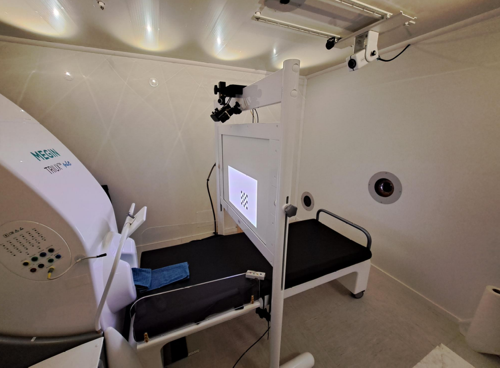
The MEG is equipped with an EyeLink 1000 Plus eye-tracker from SR Research. The eye-tracker can be used in all positions:
upright, 60° or 68°, camera below the projection screen
supine, 0°, camera above the projection screen
Setup🔗

Standalone vs integrated mode🔗
The eye-tracker can be controlled from the stimulation PC. This is the recommended approach, as it allows to customize the eye-tracker settings, calibration and visual for every experiment. However, it is also possible to use the eye-tracker in standalone mode, either without the stimulation PC or through a simple calibration and recording application on the stimulation PC.
Every paradigm should be designed to communicate with the eye-tracker directly. Bindings and examples for different software and programming languages are available on the SR Research website.
Mainly, this method increases control on the visual window displayed for calibration and recording and allows a tight integration of the calibration in the paradigm. With this method, a monitoring window can be opened during the experiment displaying a live view of the gaze position super-imposed on the paradigm.
In standalone mode, the eye-tracker can be controlled from the EyeLink PC or through a simple calibration and recording application on the stimulation PC, such as eyelink-track.
Triggers🔗
Triggers delivered to the MEG (see the section about
triggers from the stimulation PC)
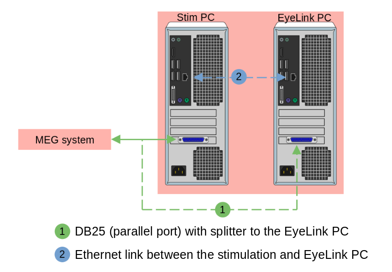
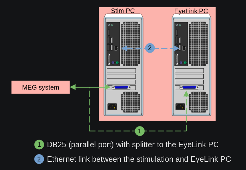
are automatically duplicated and delivered to the eye tracker on the DIN channel.
Alternatively, triggers can be delivered as a “message” via the ethernet link between the stimulation PC and the EyeLink PC.
Note
Both hardware trigger through the DB25 (parallel port) of the stimulation PC and through the Chronos are duplicated and sent to the eye-tracker.
Analogical outputs🔗
The eye tracker is capable of sending some analogical output directly into the misc
channels of the MEG, thus recording core information as part of the FIF file. In total,
6 channels are available.
In this mode, the channels correspond to the actual gaze position on the display screen. This mode requires a calibration.
0: \(X_{pos}\) (eye A)1: \(Y_{pos}\) (eye A)2: Pupil size (eye A)3: \(X_{pos}\) (eye B)4: \(Y_{pos}\) (eye B)5: Pupil size (eye B)
By default, the 3 first channels are connected to the 3 first MEG miscellaneous
channels: MISC001, MISC002, and MISC003. The information is encoded
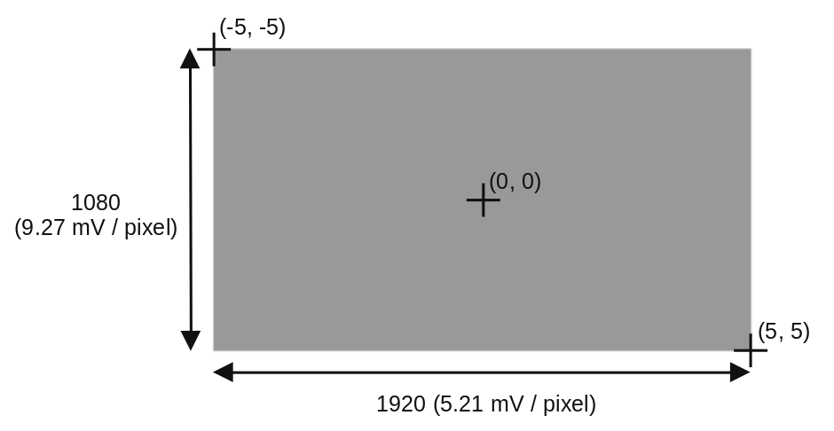
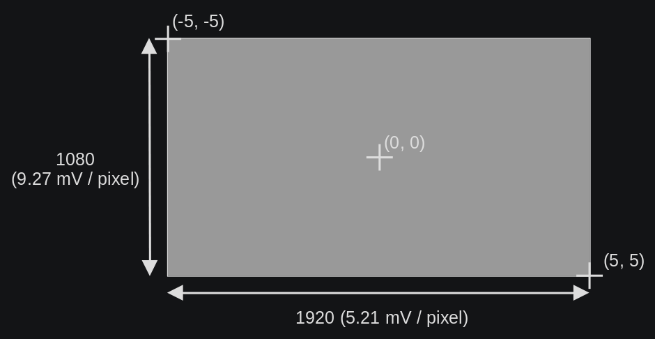
linearly on the voltage range (-5, 5) Volts. For the \(X\) and \(Y\)
position:
(-5, -5)corresponds to the top-left corner.(0, 0)corresponds to the center of the screen.(5, 5)corresponds to the bottom-right corner.
Warning
When tracking of the eye is lost, e.g. during a blink, the analogical output
drops to the minimum -5V value.
This measurement is the raw pupil-center position (or pupil minus corneal if run in pupil-CR mode) and does not require a calibration.
This measurement is related to the tangent of the rotation angle of the eye
relative to the head. For the -5V to 5V range, it’s
\(5V * tan(angle)\), measured separately for vertical and horizontal
rotations. This mode requires a calibration.