MEG triggers🔗
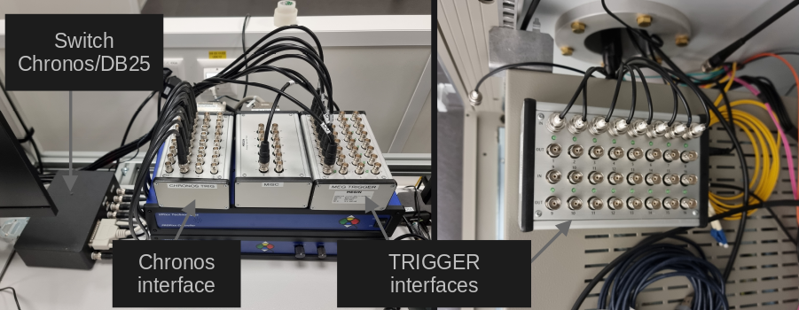
The MEG system has 32 binary channels that can be used for triggers. Those 32 channels are split between 2 trigger interface I/O boxes, one on the main desk connected to the stimulation PC and one in the stimulus cabinet.
Binary vs combined channel🔗
The channels STI001, STI002, …, STI016 are binary channels. They measure a
single TTL pulse which drives the channel from 0 to 1 and vice versa.
The channels STI101 and STI102 are combined channels which measure at once the
16 binary channels associated to their respective trigger interface I/O box. The
value measured by a combined channel corresponds to the decimal value of the binary
number expressed on the binary channels. For instance, if the channels 1, 3, 4 of the
trigger interface I/O box in the stimulus cabinet receive a pulse, the combined channel
STI101 receives the decimal value which corresponds to the binary number 1101
(from left to right, channel 4 is high, channel 3 is high, channel 2 is low and channel
1 is high). In decimal, this number equals 13.
Thus, if 8 BNC cables are connected, e.g., from the computer DB-25 port (parallel port), the combined channel can receives triggers ranging from 0 to 255 (8 bits unsigned integer). In theory, with 16 channels each, combined channels can measure trigger ranging from 0 to 65535 (16 bits unsigned integer).
STI101 and STI102🔗
STI101 and STI102 are the names of the 2 combined channels corresponding to
each trigger interface I/O box. STI101 corresponds to the one in the stimulus
cabinet and STI102 to the one on the main desk. By default, both trigger interface
I/O box work in synchronous mode. In this mode, you effectively have only 16 binary
channels, mirrored between both boxes. In other words, if a trigger arrives on the
channel 1 of the box in the stimulus cabinet, the same trigger will be received on the
channel 1 of the box on the main desk. In this mode, you need to be certain that 2
triggers will not arrive simultaneously on both trigger interfaces.
To desynchronize the trigger interfaces, the channel STI102 must be enabled. When
desynchronized, a trigger which arrives on the channel 1 of the box in the stimulus
cabinet is not mirrored on the channel 1 of the box on the main desk. When
desynchronized, the individual binary channels of the trigger interface on the main desk
are not available.
Note
STI102 is disabled by default and it is not possible to change the default. It
is however possible to create the project specific settings which have to be
reloaded at the start of every new acquisition.
Triggers from the stimulation PC🔗
The stimulation PC can send triggers to the 8 first bits
of the trigger interface on the main desk, STI102, via a parallel port (DB-25) or
via the Chronos if E-Prime is in-use. You can switch which output is
in-use with the switch Chronos/DB-25 on the main desk. See
the trigger section of the stimulation PC for additional
information.
Parallel Port (DB-25)🔗
On Windows, the address of the parallel port in hexadecimal is 2FB8. On the
desktop, LPT Port Test Utility can be used to test the parallel port.
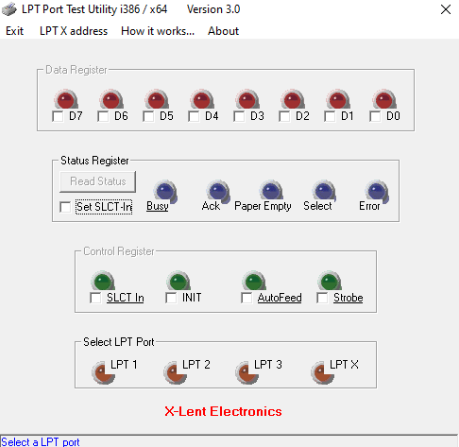
Select LPT X address and set 2FB8. You can then turn ON or OFF the
individual Data Register pins.
Note
The LPT Port Test Utility can be downloaded
here.
On Linux, the address of the parallel port is /dev/parport0.
Chronos🔗
With E-Prime, a Chronos can be used to deliver triggers. The Chronos has 16 digital inputs and 16 digital outputs, wired to the Chronos interface on the main desk. The 8 first output pins are wired to the 8 first bits of the MEG trigger interface.